TYPES OF ELECTRONICS COMMUNICATION PROTOCOLS
Inter System Protocol
- UART Protocol
- USART Protocol
- USB Protocol
Intra System Protocol
- I2C Protocol
- SPI Protocol
- CAN Protocol
Notes : I2C and SPI are the most popular modes of communication, hence we'll limit our learning to these modes of communication.
SERIAL PERIPHERAL INTERFACE (SPI)
- SPI is a synchronous data bus.
- The clock is an oscillating signal between high and a low state to coordinate actions of digital devices.
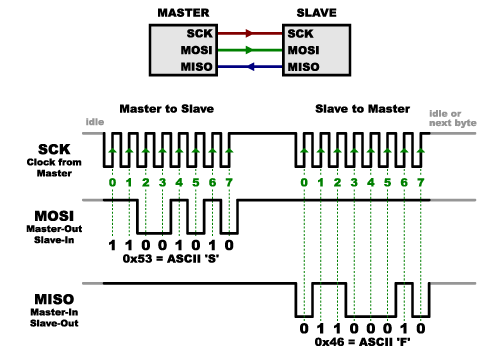
- In SPI, only one side generates the clock signal (usually called CLK or SCK for Serial Clock). The side that generates the clock is called the “master”, and the other side is called the “slave”.
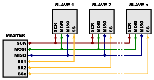
- There is always only one master, but there can be multiple slaves.
- MOSI : “Master Out / Slave In” , MISO : “Master In / Slave Out”.
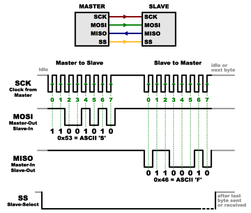
- The logic state of Slave Select (SS) line decides the start or end of the communication.
- Logic 0 of SS line indicates the start of communication. Logic 1 indicates the end of communication
- TinkerCad Demo Circuit
WITH SLAVE SELECT (SS)
WITH MULTIPLE SLAVES (SS)
I2C – INTER INTEGRATED CIRCUIT
- I2C requires two wires, like asynchronous serial, but those two wires can support up to 1023 slave devices.
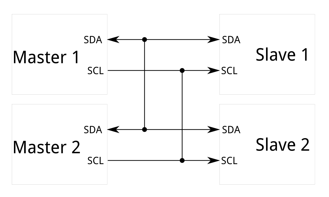
- Unlike SPI, I2C can support a multi-master system, allowing more than one master to communicate with all devices on the bus.
- Master devices can’t talk to each other over the bus and must take turns using the bus lines).
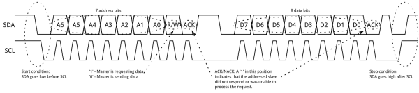
- Each I2C bus consists of two signals: SCL and SDA. SCL is the clock signal, and SDA is the data signal.
I2C - Best of both the worlds
- Messages are broken up into two types of frame: an address frame, where the master indicates the slave to which the message is being sent, and one or more data frames, which are 8-bit data messages passed from master to slave or vice versa.
- Data is placed on the SDA line after SCL goes low, and is sampled after the SCL line goes high. The time between clock edge and data read/write is defined by the devices on the bus and will vary from chip to chip.
- TinkerCad Demo circuit
References


 Electronics